
Tech Committee Pages
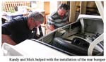
| CPPC's Technical Committee exists to keep old Plymouths on the road so people can enjoy them. What the members have in common is a love of cars that goes back to their teenage hotrod days – which for these gentlemen was some time ago. They frequently have personal collections of hard-to-get parts or a pretty shrewd idea where to find them; and by the time you have three or four of these guys together, you have a couple of hundred years of wrench-turning experience. That kind of know-how is priceless, and they make house calls if you provide the coffee and doughnuts. The Tech Committee meets whenever and wherever they might be needed. Randy Ealy heads up the Technical Committee. You can email him from here by clicking on his name, or phone him at 503 864-8111. | |
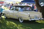 |
Phil and Rose Ann Hall drove their 1954 Plymouth Belvedere 300,000 miles before they restored it, and they have taken it on a couple of cross-country drives since then. Phil spoke at a CPPC meeting about the spare parts he takes on a road trip, and later provided a written version of his presentation. Read it at this link … |
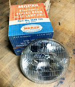 |
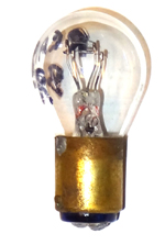
Getting all 6 volts to your 6V headlights – Arn Landvoigt offers step-by-step instructions for 6V system maintenance. Read more … |
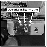 |
Overdrive Indicator Lights – here's a fairly simply way to monitor what your overdrive unit is doing. Read more … |
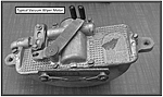 |
Vacuum Windshield Wiper Motors – how they work, how to maintain them, where to get them rebuilt. Read more … |
 |
Carter BB carburetors – some issues to keep in mind as you're rebuilding these old Mopar standbys. Read more … |
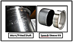 |
Repairing shaft seal leaks – a few steps to take to ensure a good seal. Read more … |
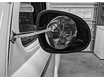 |
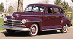
Limited vision to the rear? Authentic old-time rear-view mirrors leave a lot to be desired. Phil Lapin drives his 1942 Plymouth sedan, and likes the extra safety he gets from this modification. Read more … |
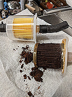 |
Fuel system rust -- here's what Phil Lapin found in the gas tank of his 1942 Plymouth. Read more … |
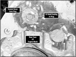 |
Another look at freeze plugs – how about brass plugs, sealed with JB Weld? Read more … |
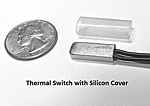 |
Buzzers and sensors – need something to watch your temperature gauge for you, or remind you when the blinker is on? Increase your confidence just a bit with these inconspicuous add-ons. Read more … |
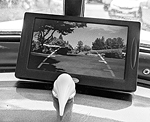 |
A backup camera in a 1942 Plymouth? Folks who intend to drive their cars a lot might appreciate the extra safety and convenience of a backup camera. Phil Lapin shopped around and came up with a reasonably-priced system and a workaround to deal with his 6V electrics. Read more … |
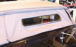 |
Enlarging the rear window of a 1935 Plymouth Convertible – Mike Bade got tired of trying to see out of the little bitty window that was stock on his '35 convertible, and decided to make a larger one. Read more … |
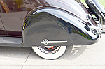 |
FENDER SKIRTS add a lot to the appearance of Mike Bade's 1935 Plymouth convertible. After getting outbid on one pair, and buying another pair that didn't fit, he made his own – and even got correct medallions from a guy in the Plymouth Owners Club who makes them out of resin. Read more … |
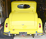 |
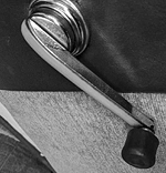
A FUEL TANK PAN cleaned up the look of Mike Bade's hotrodded 1930 Plymouth U coupe. Click on the picture of follow this link to see how he did it. |
 |
RESETTING OR RESEALING WINDOW GLASS – Relax, wear old clothes, keep lots of paper towels handy. It's going to be messy. Phil walks through the process of resetting the glass in his 1942 Plymouth. Read more … |
 |
MORE ABOUT LED LIGHTS – LEDs differ from old-fashioned light bulbs, and there are some things to consider before choosing the right one for your car. Read more … |
 |
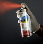
RUBBERIZING PARTS & PIECES – Phil found a good product, not particularly expensive, for rubberizing the miscellaneous bits and pieces that need a coating. The good news is, it doesn't need heat to cure. Read more … |
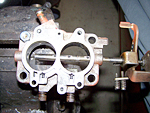 |
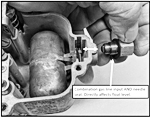
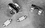
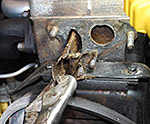
Bob Westphal's Barracuda had a lingering smell of raw fuel when the engine shut down. He found that the throttle shaft bushings are worn, causing fuel leakage on the manifold. He found a rebuild kit, and supplied pictures of the rebuild process. Read more about it … |
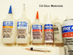 |
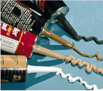
Cyanoacrylate Adhesives – "Super Glue" products, are invaluable tools for the old-car restorer. The products are also expensive, toxic, and unforgiving to work with. Here are some tips to help get the most from the. Read more about it … |
 |
Phil visits the Project Farm – a You Tube channel that answers questions familiar to anybody in the old-car hobby, plus some that we haven't thought of yet. Read more about it … |
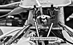 |
Gauges on the dash – calibrating the fuel gauge and oiling the speedometer cable on a 1942 Plymouth, plus a bonus way to extend a flex cable. Read more about it … |
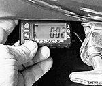 |
Cheap electronics for a 6V car – how many times did you wish you had a tachometer in the car, then thought about your 6V-positive-ground system and decided "forget about it?" Here's a workaround that's not too expensive, and not too ugly. Read more about it … |
 |
Paint Specifics – here's an overview of the products and procedures Phil used while painting the Patina Princess, step by step. Read more about it … |
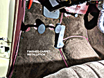 |
Installing Carpet in the Patina Princess – adding underlayment, and completing the installation to alllow access to the under-floor master cylinder. Read more about it at this link. |
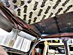 |
Adding Sound Insulation – while things were apart, Phil decided to add some sound-deading material to the Patina Princess. Read more about it at this link. |
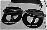 |
Replacing the rubber parts on your classic car – products you can trust. Read about it at this link. |
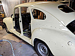 |
Do-It-Yourself Painting for the classic car owner – Phil paints The Patina Princess. Read about it at this link. |
 |
Installing a new headliner – A family of mice had made its home in The Patina Princess for generations. Step by step, here's what it took to replace the headliner in the 1942 Plymouth. Read about it at this link. |
 |
Changing voltage up and down – There are some new technical answers to the old question of wiring in your antique car. Read about them at this link. |
 |
Auto Glass & Rubber: When CPPC's Phil Lapin needed window glass for his 1942 Plymouth, he found a stellar resource fairly close to home. Read about it at this link. |
 |
Vintage Engine Startup From Storage: Bringing a long-stored engine back to life is usually less daunting than one would imagine,assuming the engine was in decent condition when it was retired years ago. This article in the CPPC Newsletter is an overview of the process steps. Read about it at this link. |
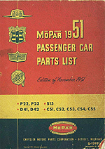 |
Parts List Books – Parts identification is a big part of restoring or rebuilding any project. One of our members, Gary Rusher, started a collection of official parts books. He would like to have a complete set covering all Plymouths up to and including the P15's or later. If you have books you'd like to donate or sell to our library, contact Phil Lapin by phone or at his email link above. Read about it at this link. |
 |
Thinking about conversion to LED lights in your classic car? Tech Coordinator Phil Lapin shares his research and experience. Read about it at this link. |
 |
Owning and restoring a classic car – Tech Coordinator Phil Lapin polled CPPC members to see what kind of guidance they have to offer to people entering the hobby. Read about it at this link. |
 |
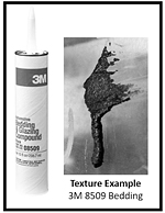
The market has a variety of sealers, adhesives, fillers, and miscellaneous goops available for purchase. Some will work better on your old car than others. CPPC's Tech Coordinator Phil Lapin took the time to discuss the main kinds of adhesives and sealants that apply to restoration/renovation or maintenance of old cars. Read about it here. |
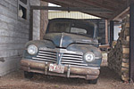 |
One of the tech guys followed up a craigslist ad and found a 1942 Plymouth Deluxe sedan in a lean-to, east of Vancouver, WA. The Tech Committee bought it, trailered it to Bob & Yvonne Westphal's garage, and went to work to get it running. A brand-new CPPC member came along, and bought it! Follow this link to see the latest on the '42. |
 |
Mike Bade purchased a new-to-him 1935 Plymouth Convertible, by all appearances a well-preserved original car, and soon discovered an overheating problem. Here's what he learned about replacing the water distribution tube in his '35. |
 |
Gary Rusher has been fighting a serious vibration problem in his 1930 Plymouth U coupe for several years. Gary has tried one thing after another to locate and quiet the vibration, sharing the trial-and-error process in CPPC's newsletter. This link takes you to all of the Rusher "bad vibration" posts. |
 |
Chuck Willis bought a 1975 Dodge Dart basket case, with random pieces of another car thrown in for good measure. He and the Tech Committee have spent a couple of years sorting things out. Here's an article about the process, with photos by Stephanie Willis. |
 |
When the original engine in Bob Westphal's 1948 Plymouth P-15 Special Deluxe Coupe finally wore out, he considered his options and decided to swap in a slant-6 and automatic transmission. Follow this link to read the story of the Tech Committee's great Slant-6 into P-15 swap. |
 |
A link to a really good article on hydraulic brakes from the 1948 Chrysler Master Technician Service Conference booklet, courtesy of The Imperial Club: follow this link! |
 |
CPPC's Tech Committee doesn't discriminate, so when member Russ Ashley's 1940 Ford needed attention, eleven members of the Tech Committee showed up to assist. There was a little drama when the starter engaged and the car started moving on its own, but it all ended well. Read about it here. |
 |
Brian Samore found a nice original 1948 Plymouth P15 Special Deluxe Sedan and put it away for safekeeping – for 28 years! Brian and a couple of Tech Committee members woke the car from its slumber, getting it lubed and making sure it would start and stop, and it had been on the road for only two weeks, on the way back from DMV with its "new" 1948 plates, when somebody ran a stop sign, hitting it hard enough to destroy the entire front clip. Here's the rest of the story. |
 |
A link to some basic nut-and-bolt dimensions that we have all needed, thanks to The Bolt Depot.com. |
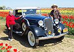 |
The late Pat Brost, shown here with spouse Patty (also deceased as of 2017) and their 1933 Plymouth PD convertible, was a frequent contributor to the CPPC newsletter with service and maintenance tips to keep keep Plymouths on the road. Here are his articles on electrical grounding and freeze plugs. |
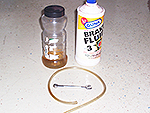 |
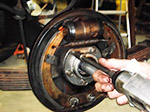
Bob Westphal has been bleeding brake systems for something like sixty years, maybe more, and he's still alive to talk about it. Read his article describing how to bleed brakes without fancy equipment. |
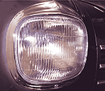 |
Between 1928 and 1939, before sealed-beam headlights were mandated, Plymouth used a variety of headlight lenses. Gary Rusher did some homework and prepared a list, and you can download it at this link. |
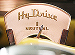 |
From mid-1953 through most of the 1954 model year, Plymouth offered Hy-Drive in lieu of a fully-automatic transmission. The fully-automatic PowerFlite became available in '54, and Hy-Drive quietly went away. CPPC member Phil Hall provided the best explication of the Hy-Drive unit that we've ever seen, and we're sharing it here. |
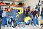 |
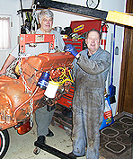
Mike Bade is a busy guy, and he was having trouble finding time to work on the hot-rod 1930 Plymouth U coupé that he had kept around since his college days. Donna Bade made a few phone calls, fixed a nice lunch, and the CPPC Tech Committee paid a "surprise" visit to the Bade garage to get things rolling. |
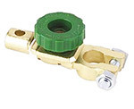 |
CPPC member Don Amundson is also a Washington State Safety Team Member with the National Hot Rod Association, an organization that takes safety seriously. Here's a a link to his article about Battery Disconnect Switches from our newsletter. |
| Back to top of page. | |